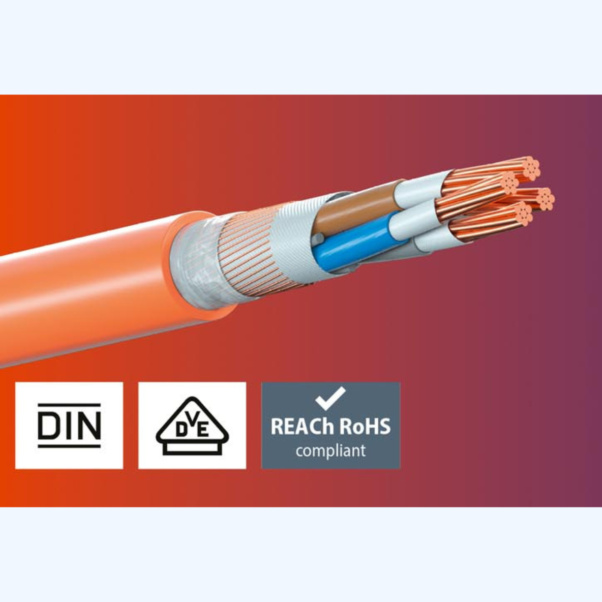
BETAflam - Fire Resistant Cable (FRC)
BETAflam Cable for Ultimate Safety. Made in Swiss, LSOH Fire Resistant Safety Cable with circuit integrity according to BS 6387 CWZ / IEC 60331 - 21

Product Value

The best Fire-resistant power cables with Copper stranded wire.

Insulation BETAflam® mineral copolymer

Made in Swiss

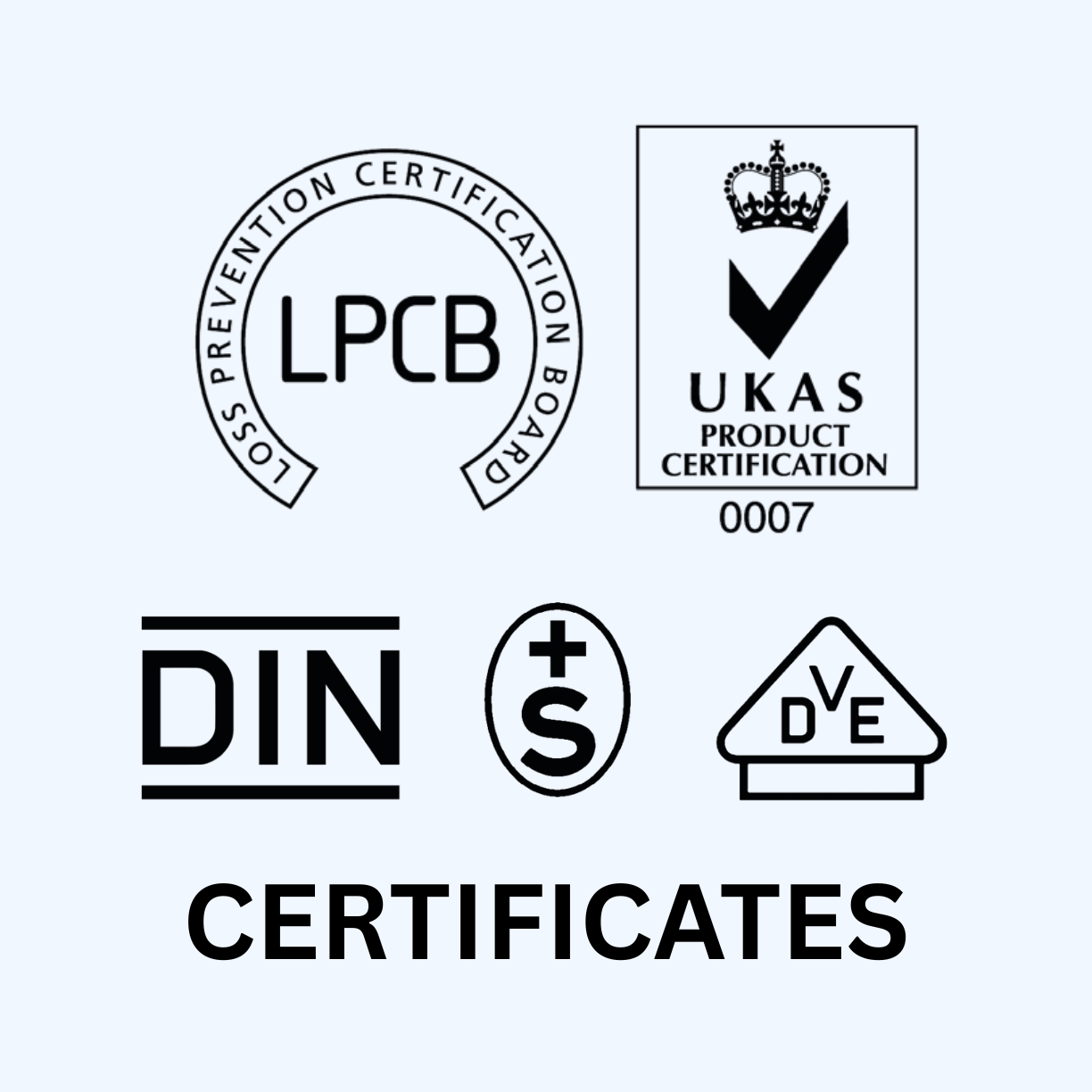
LPCB - British Standart BS 6387 C.W.Z, IEC 6387, LSOH
-
BETAflam® FR-MI 110 SCSI / Single-core single insulated - Single core wires 0.6/1 kV for cable wiring systems with the highest fire performance and circuit integrity requirements. For high temperature conditions and extra long expected lifetime.
- BETAflam® (N)HXCH FE180 / E30–E60 - Three-phase power cable 0.6 / 1 kV with concentric outer conductor for fixed installation in electrical cable systems with improved fire behaviour and system integrity according to DIN 4102 Part 12.
- BETAflam® FR-SIR-U 90 - unscreened - is an unshielded Fire Alarm Cable with excellent fire perfomance in case of fire and high circuit integrity characteristics.
- BETAflam® FR-SIR-F 90 - screened - is a shielded Fire Alarm Cable with excellent fire perfomance in case of fire and high circuit integrity characteristics.
BETAflam mineral copolymer, cross-linked
Advantages of cross-linked insulation materials
- Increased shear and compressive strength
- Improved integrity in case of electrical failures (overload, short circuit)
- Improved resistance to chemicals
- Infusible, soldering iron resistance
- Improved impact strength and crack resistance
- Better weather and abrasion resistance
- Non-flame propagating : EN 50399, EN 60332-3, IEC 60332-3, VDE 0482-266-2
- Halogen-free cables : Serie EN 60754-1, IEC 60754-1
- Corrisive effects of combustion gases : EN 60754-2, IEC 60754-2
- Smoke density : EN 61034, IEC 61034
- Flame-retardant : EN 60332-1-2, IEC 60332-1-2
- Insulation integrity under fire conditions : IEC 60331-21, DIN VDE 0472-814, BS 6387 C
- Insulation integrity when exposed to water : BS 6387 W, VdS 3423
- Insulation integrity with mechanical shock : EN 50200, EN 50362, VDE 0482-200, BS 6387 Z
- Total system integrity under fire conditions : DIN 4102, Part 12
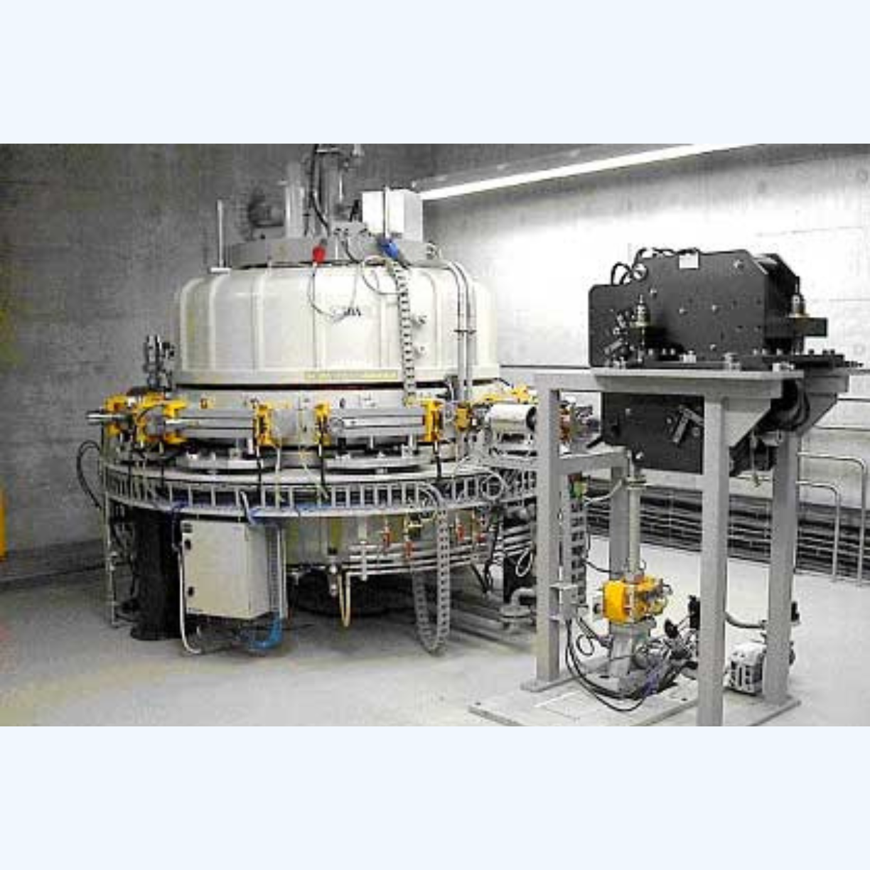
Rack-mounted AHF module
.jpg")
| Modules | AHF | SVG | Dimensions(W×D×H,mm) | Wight - Net Weight (kg) |
|---|---|---|---|---|
| 400V | 50A | 35kVar | 440*425*88 | 14 |
| 75A | 50kVar | 440*425*88 | 17.5 |
| Modules | AHF | SVG | Dimensions(W×D×H,mm) | Wight - Net Weight (kg) |
|---|---|---|---|---|
| 400V | 50A | 35kVar | 440*425*88 | 14 |
| 75A | 50kVar | 440*425*88 | 17.5 |
| Modules | AHF | SVG | Dimensions(W×D×H,mm) | Wight - Net Weight (kg) |
|---|---|---|---|---|
| 400V | 50A | 35kVar | 440*425*88 | 14 |
| 75A | 50kVar | 440*425*88 | 17.5 |
| Modules | AHF | SVG | Dimensions(W×D×H,mm) | Wight - Net Weight (kg) |
|---|---|---|---|---|
| 400V | 50A | 35kVar | 440*425*88 | 14 |
| 75A | 50kVar | 440*425*88 | 17.5 |

Static Var Generator Working Principle
The active harmonic filter operates on a 3-level neutral point clamped (NPC) topology. As shown in the figure below, the traditional 2- level topology circuit structure consists of 6 IGBTs (2 IGBT power devices on each phase pin and current path), and in the 3-level
topology, there are 12 IGBTs (in each phase 4 IGBT power devices on pins and current paths). The 3-level topology circuit can generate three voltage levels at the output, including DC bus positive voltage, zero voltage and DC bus negative voltage. Two-level topology circuits can only output positive and negative voltages. At the same time, the three-level topology circuit also ensures higher quality and better harmonic output voltage, thereby reducing output filter requirements and associated costs.
SinL-Series AHF / SVG Load Balancing For 3P3W and 3P4W
The active harmonic filter operates on a 3-level neutral point clamped (NPC) topology. As shown in the figure below, the traditional 2- level topology circuit structure consists of 6 IGBTs (2 IGBT power devices on each phase pin and current path), and in the 3-level
topology, there are 12 IGBTs (in each phase 4 IGBT power devices on pins and current paths). The 3-level topology circuit can generate three voltage levels at the output, including DC bus positive voltage, zero voltage and DC bus negative voltage. Two-level topology circuits can only output positive and negative voltages. At the same time, the three-level topology circuit also ensures higher quality and better harmonic output voltage, thereby reducing output filter requirements and associated costs.
Advantages of 3-Level Topology
The active harmonic filter operates on a 3-level neutral point clamped (NPC) topology. As shown in the figure below, the traditional 2- level topology circuit structure consists of 6 IGBTs (2 IGBT power devices on each phase pin and current path), and in the 3-level
topology, there are 12 IGBTs (in each phase 4 IGBT power devices on pins and current paths). The 3-level topology circuit can generate three voltage levels at the output, including DC bus positive voltage, zero voltage and DC bus negative voltage. Two-level topology circuits can only output positive and negative voltages. At the same time, the three-level topology circuit also ensures higher quality and better harmonic output voltage, thereby reducing output filter requirements and associated costs.
| Text | 400 |
| Grid Voltage Range | -15%~- +15% |
| Rated Current (A) | 30、50、75、100、150 |
| Frequency (Hz) | 50/60Hz (-10%~+10%) |
| Harmonic Current Compensation Range | 2nd to 50th Harmonic Order |
| Efficiency | 98,5% |
| CT Configuration | Closed or Open Loop (Open Loop is Recommended in Case of Parallel Operation) |
Used By


SinL-Series Pro AHF & SVG Smart Power Solution
Catalog Berhasil Didownload
Terima kasih telah mengunduh catalog kami.Silakan cek email untuk catalog. Jika tidak menemukan email, pastikan untuk memeriksa folder Inbox, Spam, atau Promotions.
SinL-Series Pro AHF & SVG Smart Power Solution
