OPTIMUS Pro - Busway Trunking System
OPTIMUS Technology Co., Ltd., based in Taiwan, has long invested in the research, development, and sale of electrical equipment. It has a factory located in Yangzhong City, Jiangsu Province, China. Our products have obtained internationally recognized certifications, such as KEMA/KEMA KEUR, UL, and CCC, to establish a comprehensive quality management system. In addition, we are ISO9001 certified to ensure quality and provide superior products and comprehensive services to our customers.
Product Value

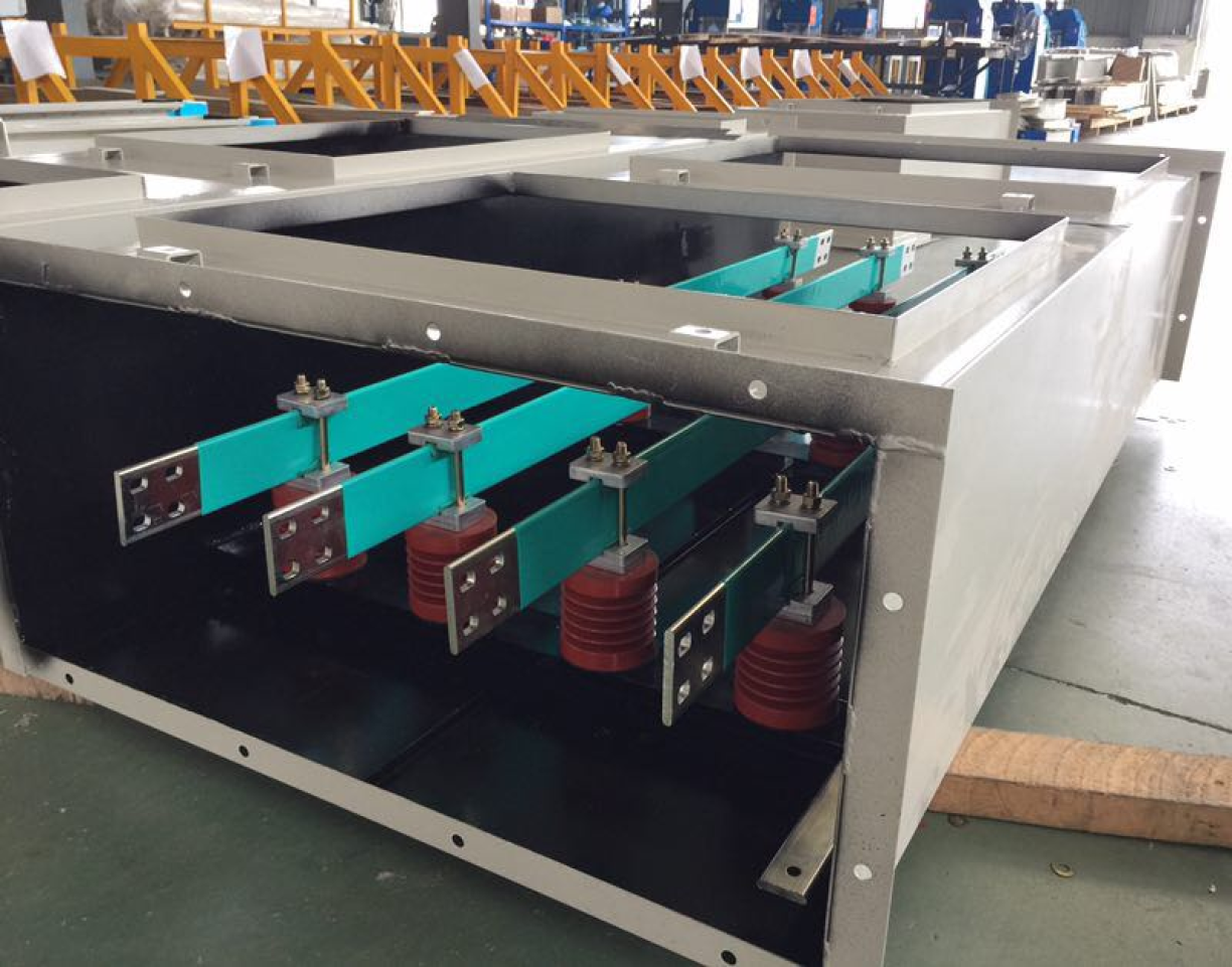
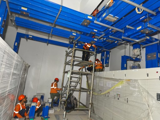
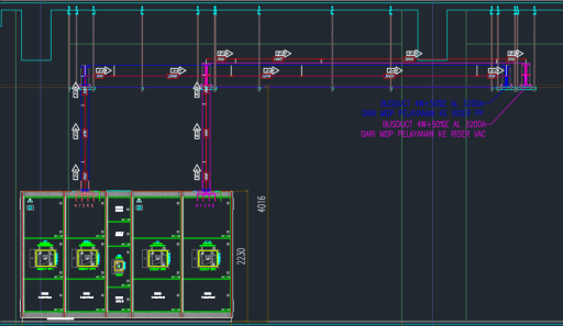
Function: Convey and distribute electricity from the transformer to the panel, from the generator set to the panel, or from panel to panel.

Commonly used in: Commercial buildings, factories, malls, data centers.

Current capacity from 400A to 6300A

Waterproof intensify busway uses Epoxy coating (Class H) and it has been successfully tested with UL 94 V-0 and successfully passed 36 cycle thermal shock test in accordance with IEC60068-2-14 and EU ROHS certificate.
Materials :
- Aluminium Extrusion
- Cold Rolled Steel
- Electro-galvanised Steel
- Stainless Steel Sheet
Performance :
- Ground Capacity : 50% or 100%
- Protection IP Degree : IP40/IP42/IP54/IP55/IP65/IP66/IP67/IP68
- The Metal Housing passed 1,800 hours of salt spray test
- Copper Busbars have high conductivity (>99.99%) with high purity (>99.97%), tin or silver-plated.
- Aluminium bars have conductivity > 58% ~ 61%, Copper plated and tin or silver-plated for contact aluminium system.
- Normal busway uses the whole warp in Mylar film of the Class B (130 'C) or Class F (155 'C), providing insulation riser configuration has been successfully tested for preventing flame propagation by IEC 60332-3 : 1992, GB/T 18380.3:2001 and fire barrier in building penetration of preventing ISO 834.
- Fire rated busway uses the whole warp in Mica film of insulating material, and has been successfully tested for 840 'C 30 minutes of fire proof resistance of JIS C8364, JIS A1304,GA/T 537, CNS 14286 and CNS 12514.
- Waterproof intensify Busway uses Epoxy Coating of the Class H (180 'C), has been successfully tested for IP68 protection of IEC 60529 and comply by UL 94 V-0, EU ROHS.
- The IP68 busway uses all layers of Cast Resin.
Rack-mounted AHF module


SPESIFICATION AND DATASHEET PRODUCT
Busway Trunking System
Country of Brand : Taiwan
Country of Manufacture : Zhenjiang, China
Company name : Mega Technology Co, Ltd.
Sole Distributor Indonesia : PT. Phanindo Mitra Abadi (ISO 2015 – 90001)
Merk Product : PRO Optimus Busway
Standard : IEC 61439-1 & 6, UL 857/ UL 1709, IEC 604391&2, IEC 60331/60332, IEC60529, GB7251.1-2005/GB7251.2-2006, JIS C8364 / JIS A1304, IEE/IEEE, NFPA 70, NEMA BU1, ISO 9001/2008
Type Test Authority : KEMA, KEMA KEUR, DEKRA, UL, CE, CCC, NCREE
Degree of Protection : IP 55 (Sandwich)
Short Circuit Rated : 85KA – 100KA
Plug in Unit MCB Brand : By Request.
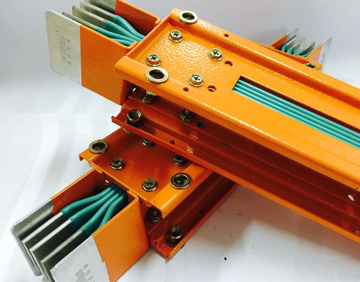
COMPACT SANDWICH BUSWAY
- Housing Type : AE (Aluminium Extrusion)
- Insulation Type : Epoxy (Class H 180 ͦC)
- Conductor Type : Aluminium (AL) or Copper (CU)
- Rate Current : 400A – 6300A
- Rate Voltage : 380V - 1000V
- Frequency : 50/60 Hz
- Housing Colour : Orange (Standard) / Customized (Max 2 Colour)
- Certification : KEMA, KEMA KEUR, DEKRA
- Salt Spray : DEKRA 6000836-02.50QS
- Epoxy Class - H : SGS HCD0192A/2017
- UL : UL-857
- IEC : IEC 61439-6
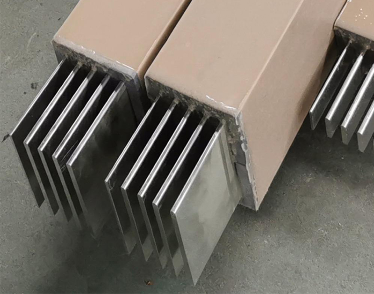
1. AE (Aluminium Extrusion),
The Aluminum Extrusion (AE) housing used in Optimus bus ducts is made of aluminum that has been extruded to form the bus duct housing.
Advantages of AE Housing:
- Lightweight
- Good electrical conductor
Disadvantages:
- Prone to denting
- Low melting point
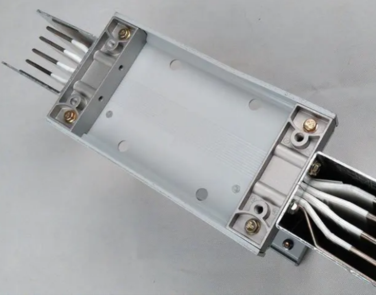
2. CS-S (Cold Rolled Steel),
The Cold-Rolled Steel (CS-S) housing used in Optimus bus ducts is made of steel that is processed using CNC machines and a bending process to form the bus duct housing.
Advantages of CS-S Housing:
- Strong and Sturdy
- High Melting Point
Disadvantages:
- Heavy
- Not a good electrical conductor
3. CS-A (Aluminium Alloy),
The CS-A aluminum alloy housing used in Optimus bus ducts is made of aluminum that is machined using CNC machines and bent to form the bus duct housing.
Advantages of the CS-A Housing:
- Lightweight
- Electrically conductive
Disadvantages:
- Prone to denting
- Low melting point
1. Mylar Class B (130°)
Mylar polyester insulation can withstand temperatures up to 130°C; the Mylar insulation process involves manually winding three layers of insulation between each conductor
2. Epoxy Class H (180°)
Epoxy insulation can withstand temperatures up to 180°C. The epoxy insulation process involves three dips using an epoxy dipping machine.
3. Mica Tape Fire Rated (970°)
Mica tape insulation has a heat resistance rating of up to 970°C for fire-rated bus ducts; however, this fire-rating applies only to copper (CU) conductors and cold-rolled steel housings (CS-S type), as the melting points of copper and steel can reach 1000°C. The mica tape is applied by manually wrapping a double layer around each conductor.
Used By


SinL-Series Pro AHF & SVG Smart Power Solution
Catalog Berhasil Didownload
Terima kasih telah mengunduh catalog kami.Silakan cek email untuk catalog. Jika tidak menemukan email, pastikan untuk memeriksa folder Inbox, Spam, atau Promotions.
SinL-Series Pro AHF & SVG Smart Power Solution
